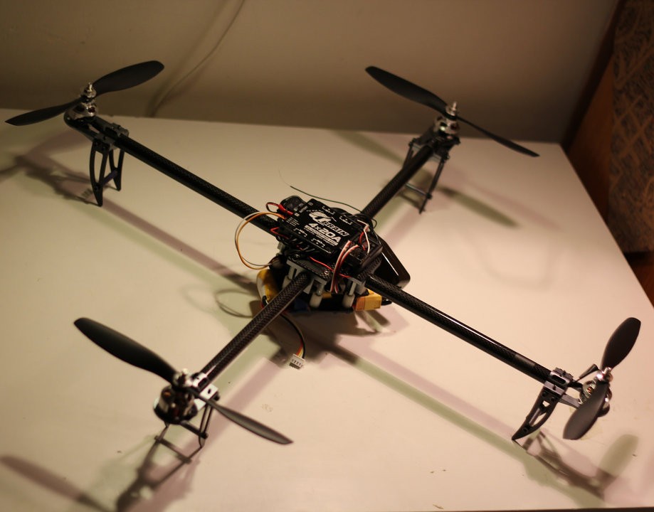
The name ‘drone’ is rather inexact and lazy; it implies illicit activities. The proper term is ‘quadcopter,’ a rotary-wing aircraft with four main rotor systems and no tail rotor.

My friends and I were fascinated by how versatile these things are so we decided to try to build these things from complete scratch in the summer of 2013. We had no idea how they worked, and we later found out that programming them required Calculus, a class some of us haven’t taken yet. Naturally, we made mistakes but we learned so much from this project.
So there’s three common elements of robots: sensors, effectors, and the control system. The sensors gather information about the environment, effectors actually do the work and change the environment, and the control system. determines the behavior.
Our quadcopter was able to tell its position in space with a sensor called an inertial measurement unit (IMU). An IMU consists of an accelerometer, a gyroscope, and a magnetometer. These three sensors have measurements along the three coordinate axes. Contrary to its name, the accelerometer doesn’t measure acceleration. It measures the force per unit mass along each axis. That means that if I held an accelerometer with its z-axis vertical, the raw measurement on the z-axis will be roughly the same as 9.8m/s2, the acceleration due to gravity. We can use this sensor to find the direction of gravity as long as the quadrotor isn’t accelerating.
Gyroscopes don’t measure the angle of an object, but rather the speed of rotation of an object. Quadcopters use this to predict how fast they’re turning in the air and adjust accordingly to stabalize themselves. Magnetometers are used to find the direction of a magnetic field at a point in space.
Unfortunately, these sensors aren’t perfect. There’s a lot of noise when flying that can mess up the readings, and things like numeric integration naturally cause readings to drift over time. This is where the control system, the microcontroller, comes in. We can use filtering algorithms to smooth out the noise and produce estimates of variables. We also used a proportional-integral-derivative controller (PID controller) to achieve a stable flight. In short, PID controllers are closed loop feedback control systems that calculates the ‘error value’ between a measurement & a desired setpoint and tries to minimize the error by adjusting other variables. For instance, if a quadcopter measures itself to be at an angle of 30° and the setpoint is 0° (completely level), it’ll have to tell some rotors to turn faster in order to level itself.
Other parts we used were a carbon fiber frame, a Q Brain Quadruple ESC, four brushless motors & rotors, and a battery.
Tech: Arduino, Electrical Engineering